Solved draw a circuit diagram of the serial adder showing Adder serial state finite electronics fsm machines diagram register block tutorial Assignment in class the serial adder was analyzed as
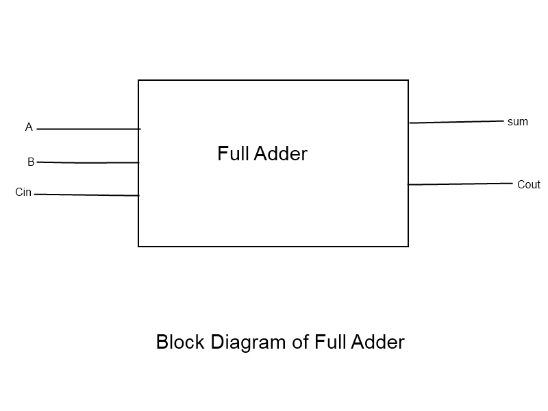
Full Adder : Circuit Diagram, Truth Table, Equations & Verilog Code
8 bit serial adder circuit diagram Full adder in digital electronics Serial-adder finite state machines || electronics tutorial
Solved design a control fsm for a 4-bit serial adder
4 bit adder subtractor circuit diagramAdder logic gates theory binary circuits numbers bits nand calculator equations along Solved in this experiment we will realize serial adderFull adder circuit diagram using ic.
Consider the sequential circuit implementing a serialFull adder circuit: theory, truth table & construction Full adder conbinational circuit9.8 sequential serial adder.

4-bit full adder circuit diagram
Adder serial binary4 bit serial adder circuit diagram 8 bit full adder circuit diagramFull adder : circuit diagram, truth table, equations & verilog code.
Solved 1. a block diagram of a serial adder is shown inBinary adder and parallel adder How to build a full adder circuitDesign a 4 bit serial adder detailed schematic (based on the.

Adder sum
Adder circuit full diagram basic gates using truth tableMoore adder fsm serial mealy diagram state type using vhdl Binary adder circuit diagram8 bit serial adder circuit diagram.
9.8 sequential serial adderDesign a serial adder circuit using verilog Noobrent.blogg.seAdder verilog.

Adder serial flip flop binary parallel flipflop use here electronics taken stack serially
Serial adderSerial adder with accumulator and serial subtractor Serial adder using mealy and moore fsm in vhdl – buzztechAdder accumulator fsm signal.
8 bit serial adder circuit diagramModule 5-serial adder Verilog code for serial adder circuit4-bit serial adder/subtractor with parallel load – altynbek isabekov.

Design of a serial binary adder
8-bit adder circuit diagram .
.


9.8 Sequential Serial Adder - Introduction to Digital Systems: Modeling

Serial Adder using Mealy and Moore FSM in VHDL – Buzztech

Full Adder : Circuit Diagram, Truth Table, Equations & Verilog Code

Verilog Code For Serial Adder Circuit - spiritfasr

9.8 Sequential Serial Adder - Introduction to Digital Systems: Modeling

Serial Adder With Accumulator and Serial Subtractor
Full Adder Conbinational Circuit | All Computer Topics
